A. 10 Gbps full-link interconnect 3D modeling
This 10Gbps link is for a complete system: UltraSerial 10G DUT Path Model
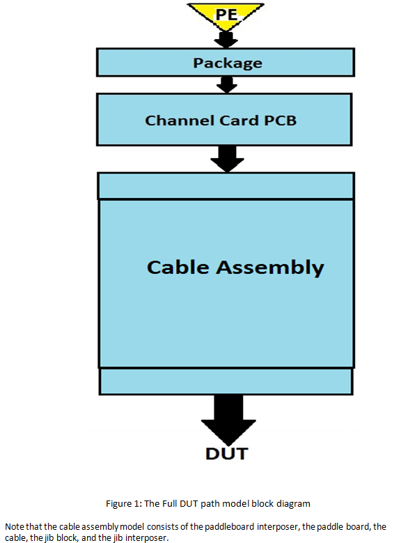
The UltraSerial10G DUT Path Model consists of all the pieces of the DUT path from the final output stage of the Pin Electronics (PE) driver up to the interposer that launches into the DUT PCB. The model elements are all passive save for the output stage of the pin electronics driver. The features of the model include:
- The PE driver has been mimicked using a voltage source with matching parasitics. The swing, data pattern and frequency can be adjusted to the user's requirements by modifying this voltage source. The model has a choice of driver's pre-emphasis equalizer's setting files that allow a user to select minimum or maximum pre-emphasis for a particular data's eye in the interconnect.
- The passive portion of the full path model consists of the package model, the channel card PCB model, and the cable assembly model, which launch into the DUT board. All of these passive models are located in the SPICE's .inc files. A block diagram of the full path model is shown in Figure 1.
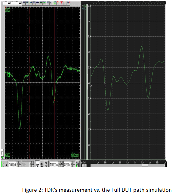
Figure 2 is the comparison of the zoom-in waveforms from the TDR's measurement of the full DUT path as shown in Fig. 1 above, to the simulation. The left plot is the TDR's measurement, and the right is the simulation's result; they are in good agreement (slight different peaks due to a special inductance of connector adaptor, not available in the simulation model.). The PE pad (as in the compare path model) is terminated with a matched 50ohm resistor.
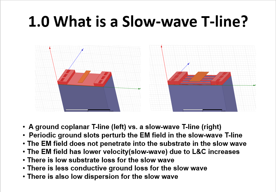
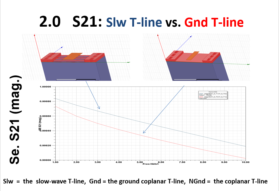
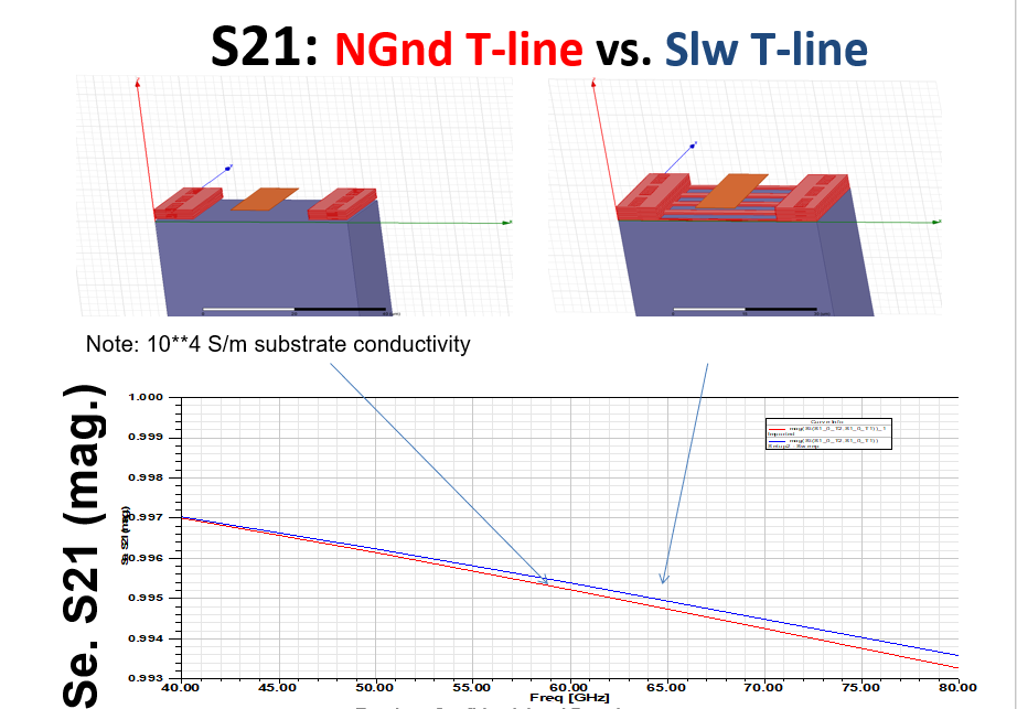
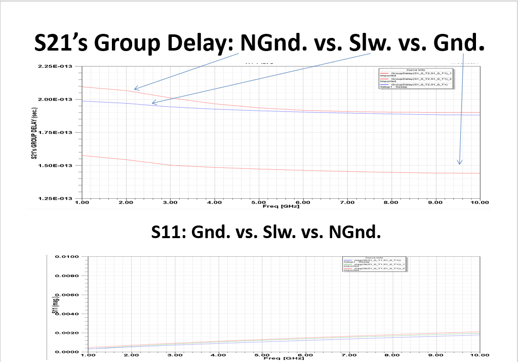
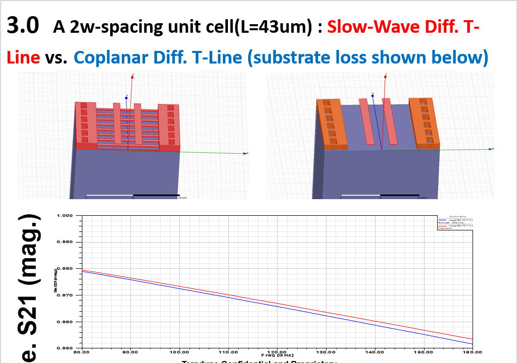
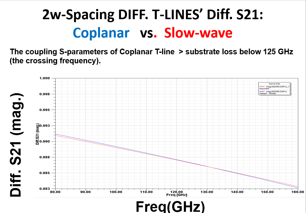
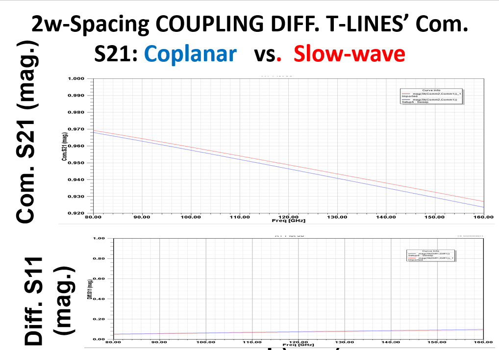
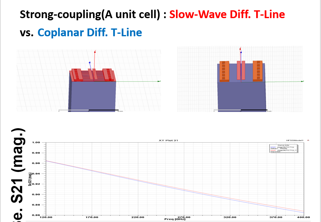
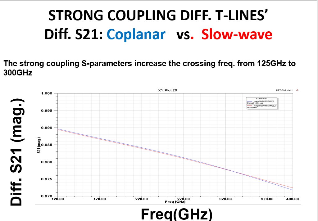
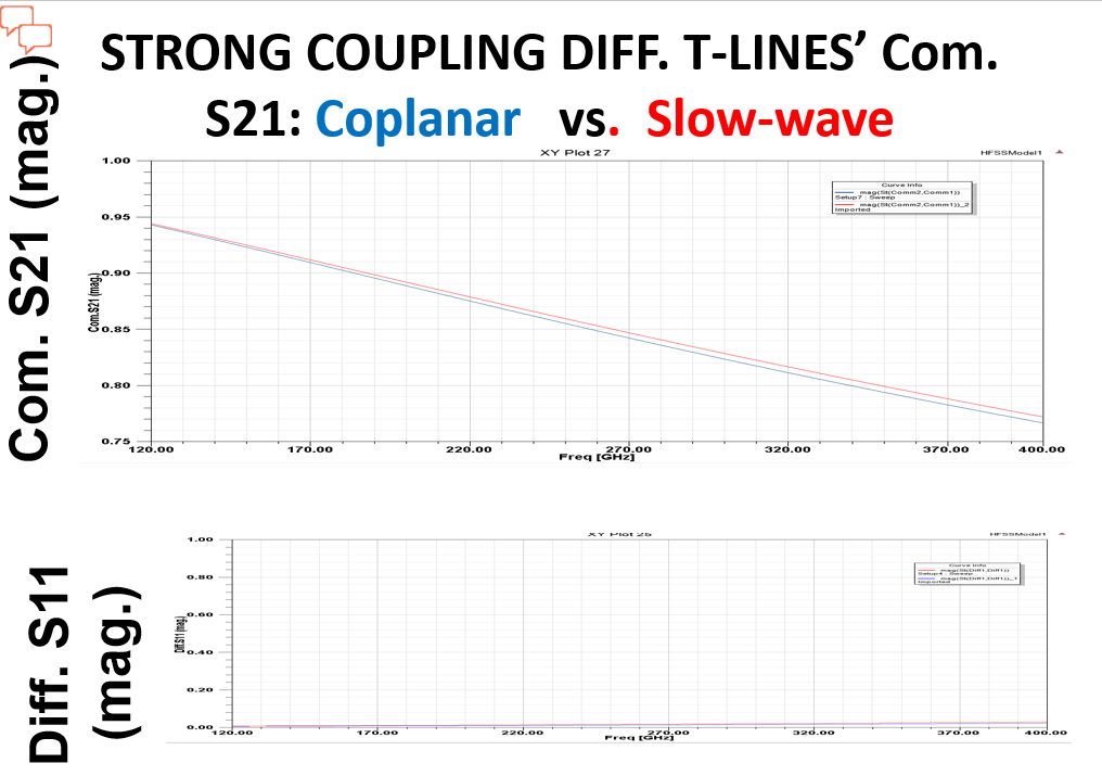
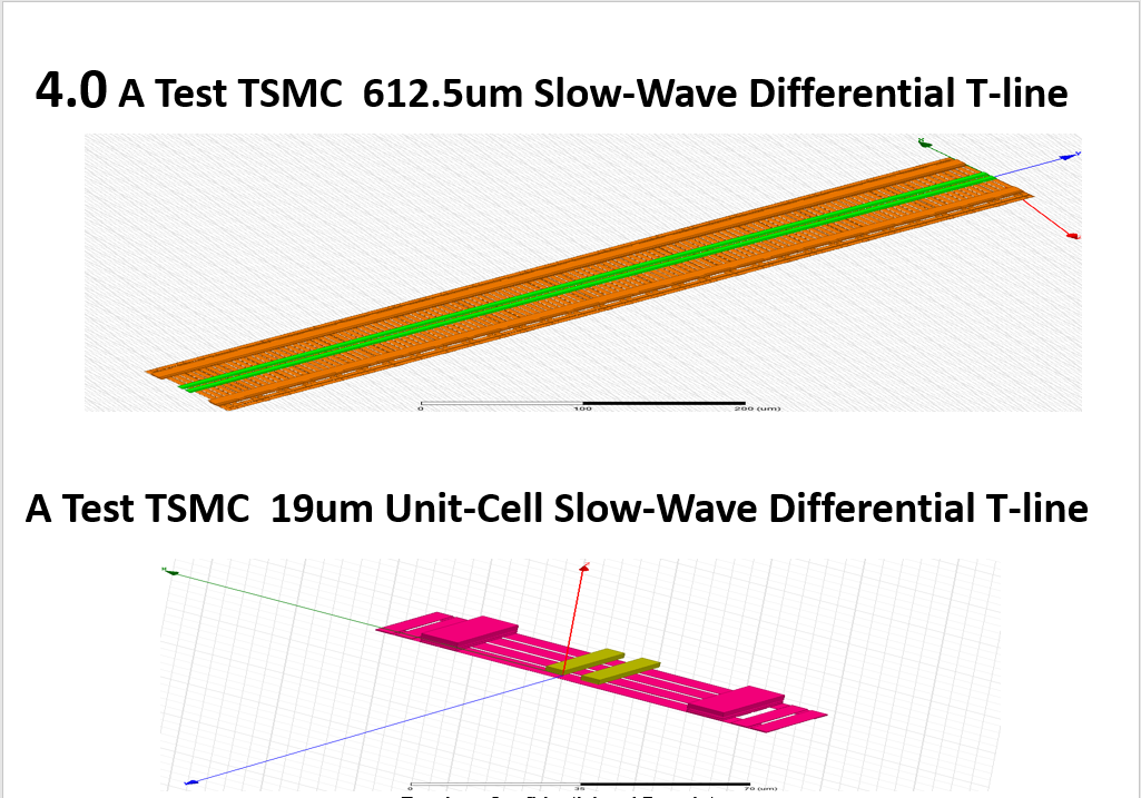
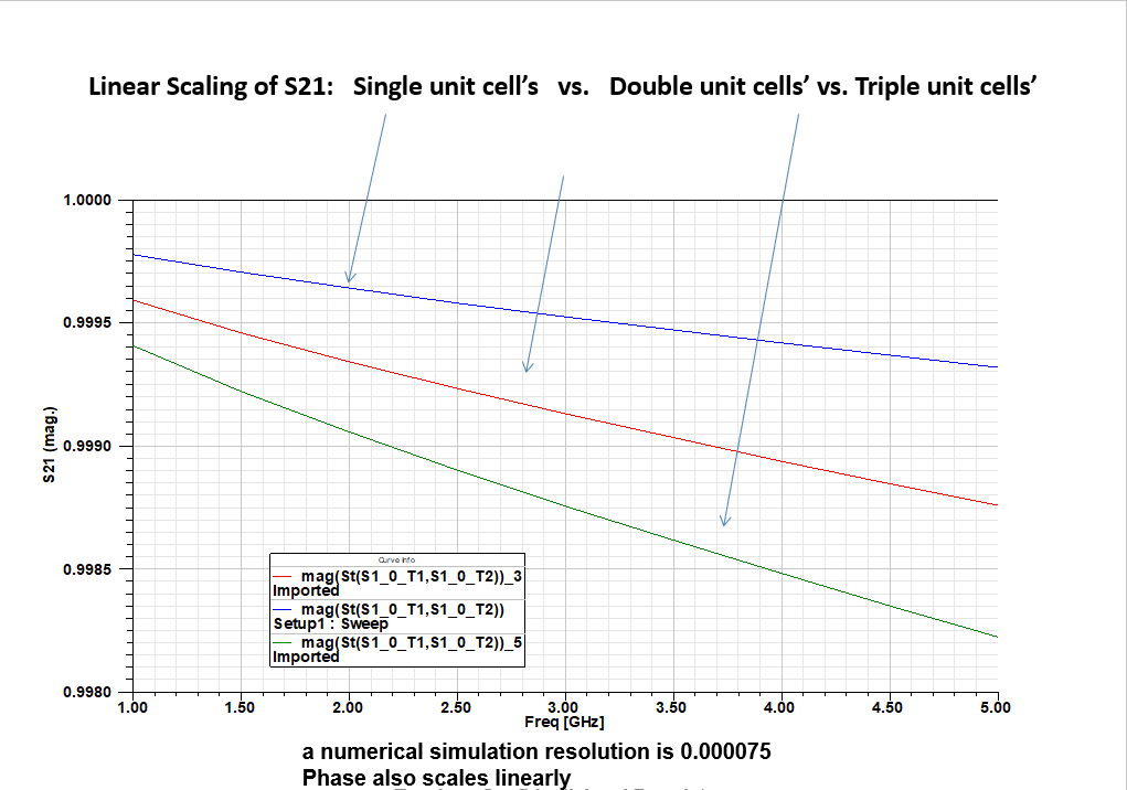
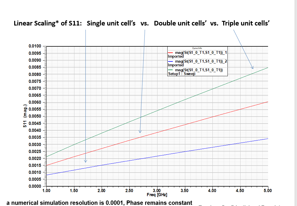
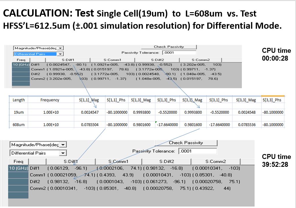
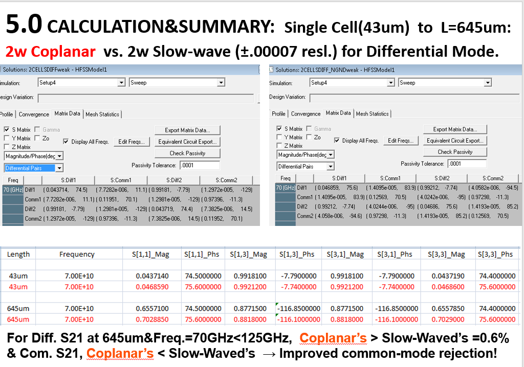
B. Slow-wave differential T-line bus 3D modeling: a unit-cell based
Slow-wave transmission lines have low losses, so they are useful to transmit signal such as clock signal across long distance. Due to its complex structure of ground rail-road-alike track, 3D simulations of even a few tenth of micron length will take too long a time or may even not converge. However, because of its periodic structure, only a unit cell of one period in length need to be simulated. The resulting S-parameters of a unit cell, can be extended to cover the whole length of the slow-wave T-line, by linear multiplication etc. The S-parameters of the full-length slow-wave T-line can then be used to generate a time-domain SPICE model for transient simulations etc.
C.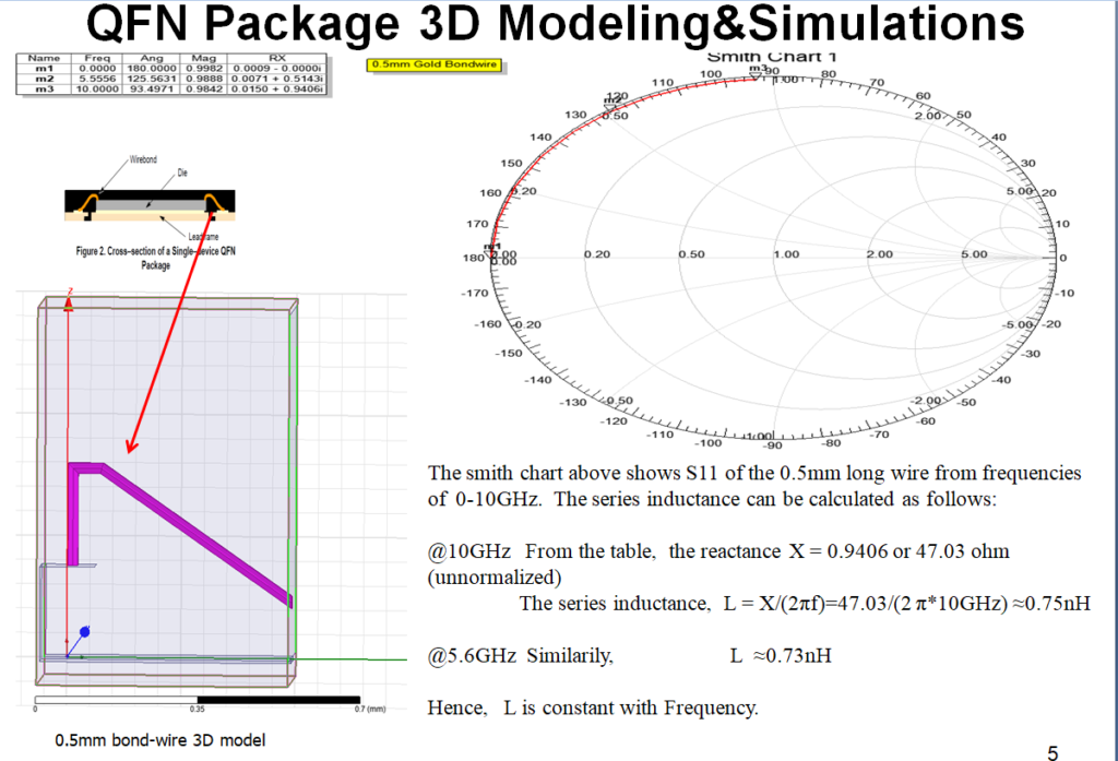 Package's bond wire 3D modeling&extractions
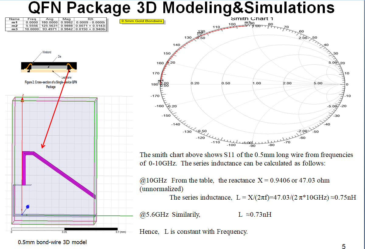
Package's parasitics such as bond wires' inductances are important for signal integrity. Bond wires' inductances cause losses, crosstalk noises, and inter-symbol-interferrence for high-speed signals. Therefore, bond wires' inductances require accurate 3D modeling&extractions for analysis simulations of their effects.
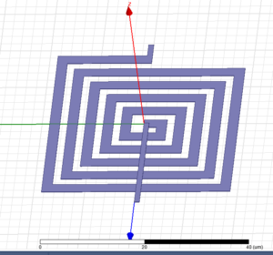
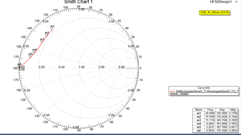
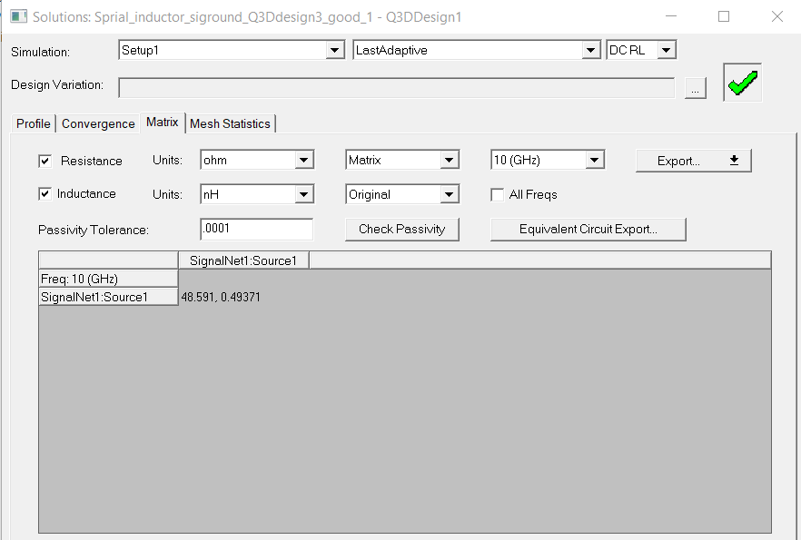
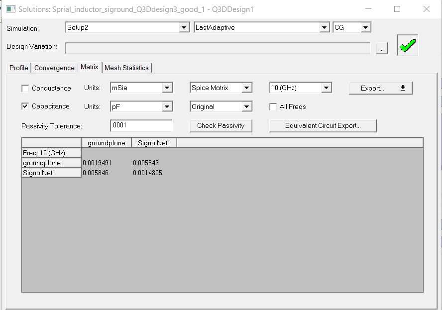
D. Spiral Inductor 3D Design&Analysis
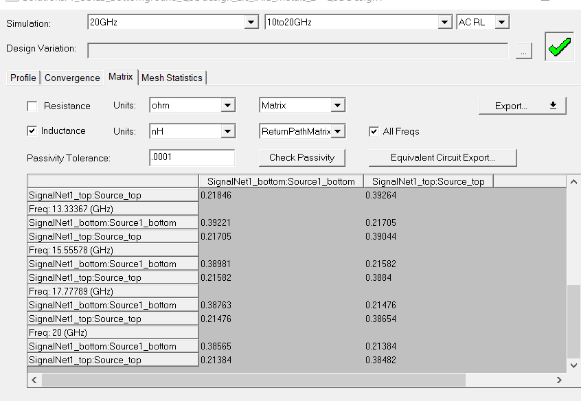
Inductors are very important components in RF and MM ICs. They must be design correctly and accurately using 3D model&simulations: their Q values and self-resonant frequencies are critical for their performances. Also, the substrate losses must be minimized by correct ground shieldings. The Ansys's Q3D extraction tool is used in order to obtain R,L,C&G matrices, as shown on the bottom left. The top left is the 3D model of a on-die spiral inductor; the middle left is the HFSS' smith chart plot of the S11 of the inductor. Note the L values from HFSS and Q3D agree well.

E. Novel Broad-sided Coupling T-Coil Design
The novel broad-sided coupling T-Coil's 3D model is shown on the left. The first coil is slightly shifted to left of the second coil in order to make the desired coupling constant, K. The first coil and the second coil have exactly identical dimensions so that their inductances are essentially the same. The first coil can be connected to the second coil using vias and traces, so that the corresponding T-coil is formed. The novel broad-sided coupling T-coil has advantages over the traditional lateral coupling T-coil in its smaller size and its accurate coupling constant, K. T-Coils have been used in RF IC in order to enhance the data transceivers' I/O bandwidth etc.
Also shown on the left, are the Q3D extraction of the T-Coil's loop inductance matrix, and resistance matrix.